Home > Tech Gallery > In-depth Explanation of PoE(Comprehensive Guide to PoE Technology)

Time: August 22nd, 2024


I. Technical Background
With the rapid development of IoT technologies, the types and numbers of smart terminals have increased sharply. The traditional high-voltage power supply is gradually losing its appeal against diversified intelligent terminals. Power over Ethernet (PoE) technology effectively resolves this problem. This article explores the history and implementation principles of the PoE technology, as well as its benefits in current network applications.
PoE provides DC power to IP-based devices, such as VoIP phones, access points (APs), and network video recorders (NVRs), while transmitting data signals. This is achieved without any modifications to the existing Ethernet cabling structure. PoE not only maintains compatibility with existing Ethernet devices but also eliminates the need for traditional procedures such as trenching and cable routing. This significantly shortens the construction cycle and reduces costs.
PoE provides DC power to IP-based devices, such as VoIP phones, access points (APs), and network video recorders (NVRs), while transmitting data signals. This is achieved without any modifications to the existing Ethernet cabling structure. PoE not only maintains compatibility with existing Ethernet devices but also eliminates the need for traditional procedures such as trenching and cable routing. This significantly shortens the construction cycle and reduces costs.
Ⅱ. Roles in a PoE System
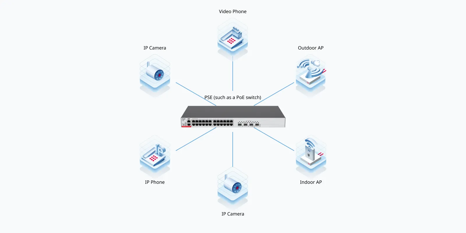
A PoE system involves two roles:
● Power Sourcing Equipment (PSE): provides power, such as a PoE switch or PoE injector. A PSE supplies power to terminals, such as wireless APs and VoIP phones, through Ethernet cables.
● Powered Device (PD): receives power over Ethernet cables.
Ⅲ. Evolutionary History of PoE
PoE has been in use for a considerable time, but there were initially no standards for its implementation. The IEEE 802.3 working group standardized the PoE technology in 2003, which led to the development of the following standards: IEEE 802.3af, IEEE 802.3at, and IEEE 802.3bt.
● IEEE 802.3af (PoE)
The IEEE 802.3af standard specifies power detection and control mechanisms in remote power supply systems. It defines methods for routers, switches, and hubs to deliver power to terminals such as VoIP phones, security systems, and wireless APs through Ethernet cables. Devices compliant with the IEEE 802.3af standard can receive up to 15 W of power.
● IEEE 802.3at (PoE+)
With higher power requirements for devices such as wireless APs, video phones, and video surveillance systems, the maximum PoE power is no longer sufficient. To address this issue, the IEEE 802.3at standard was released in 2009. This standard enables the PSE to provide up to 30 W of power through Cat5 or higher-category cables, while maintaining compatibility with IEEE 802.3af.
● IEEE 802.3bt (PoE++)
To meet the demands for even more power, the IEEE 802.3bt standard was developed. This standard is compatible with both IEEE 802.3af and IEEE 802.3at and supports an output power of up to 90 W as well as data transmission. This represents a significant increase over the 30 W power limit of PoE+.
With the higher power capabilities of IEEE 802.3bt, developers can easily add more functions and upgrade existing products, and the power requirements can be met for high-power devices used in applications such as surveillance, access control, information dissemination, parking systems, and even laptops and televisions.
Compared with the IEEE 802.3at (PoE+) standard, IEEE 802.3bt introduces two additional power supply modes, providing an output power of 60 W and 90 W, respectively. The PSE offers a wider range of output power, which can be selected according to the PD’s requirements.
The following table compares the three PoE standards.
Power Supply Technology | PoE | PoE+ | PoE++ |
Power supply standard | IEEE 802.3af | IEEE 802.3at | IEEE 802.3bt |
Power supply distance | 100 m (328.08 ft.) | 100 m (328.08 ft.) | 100 m (328.08 ft.) |
Class | 0-3 | 0-4 | 0-8 |
Max. current | 350mA | 600mA | 1730mA |
PSE output voltage | 44 V DC~57 V DC | 44 V DC~57 V DC | 44 V DC~57 V DC(Type 3 PSE) 52 V DC~57 V DC(Type 4 PSE) |
PSE output power | ≤ 15400 mW | ≤ 30000 mW | 60000 mW(Type 3 PSE) 90000 mW(Type 4 PSE) |
PD input voltage | 36 V DC~57 V DC | 42.5 V DC~57 V DC | 39.9 V DC~57 V DC |
Max. PD power | 12950 mW | 25500 mW | 51000 mW(Type 3 PSE) |
Cable requirement | N/A | Cat5e or higher-category Ethernet cable | Cat5e or higher-category Ethernet cable |
Power cable pairs | 2 | 2 | 4 |
▲Table 1: Comparison of Three PoE Standards
IV. How Does PoE Work?
PoE Workflow

● Detection
The PSE sends voltage pulses ranging from 2 V to 10 V through a port to check if the connected device is a standard PD. The PSE proceeds to the next step only when a standard PD is connected.
● Classification
Since PDs have different power requirements, the PSE must determine the power class of the connected PD, and classifies the PD. The PSE applies a detection voltage between 15.5 V and 20.5 V (limited to below 100 mA) to the PD. The PD uses the classification resistance connected to the line in series to signal its power requirements. The PSE determines the PD class based on the returned characteristic current.
Note: The default class is 0.
PoE Technology | PoE | PoE+ | PoE++ | ||||||
PD class | 0 | 1 | 2 | 3 | 4 | 5 | 6 | 7 | 8 |
PSE power (W) | 15.4 | 4 | 7 | 15.4 | 30 | 45 | 60 | 75 | 90 |
PD power (W) | 13 | 3.84 | 6.49 | 13 | 25.5 | 40 | 51 | 62 | 71 |
▲Table 2: PD Classes and Corresponding Power
● Power up
After detecting and classifying the PD, the PSE initiates power supply, sourcing 44 V DC or 57 V DC power to the PD.
● Power supply
The PSE supplies stable and reliable DC power based on the PD class.
● Disconnection
If the cable connected to the PD is removed or PoE is disabled on the switch port through software, the PSE stops supplying power to the PD within 30 ms to 40 ms. Additionally, if a short circuit occurs at any time, if the power consumed during classification exceeds the PSE's power budget, or if the consumed power surpasses the limit of the corresponding class, the entire power supply process is interrupted and restarted from the detection phase.
Ⅴ. Summary
With the continuous progress of the PoE technology from IEEE 802.3af to IEEE 802.3bt, we have witnessed a significant improvement in network power supply capabilities and expansion of its application scope. PoE simplifies network deployment, reduces costs, and improves network flexibility and reliability, especially in rapidly developing fields such as IoT and smart cities.
Campus switches provided by leading vendors such as Ruijie Networks will continue to play a key role in various industries, achieving full-scenario coverage and providing more stable and secure power supply.
Featured blogs
Related Products
-
RG-S5310-48GT4XS-P-E 48-Port GE Layer 3 Managed Access Switch with PoE+, 4-Port 10GE Uplink
-
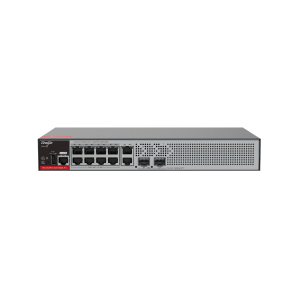
RG-S5000-10GT2MS-E 10-Port Gigabit Layer 2+ Managed Switch with Two 2.5GE Uplink SFP Ports
-
RG-CS83-48GT4XS-PD 48-Port 1GE RJ45 Layer 3 Managed Access Switch with PoE+, 4-Port 10GE Uplink
-
RG-S2915-10GT2MS-P-L 10-Port 1GE RJ45 Layer 2+ Managed PoE+ Switch, 2-Port 2.5GE Uplink